Microfluidics
Electrohydrodynamic Micromixing
Active micromixer includes an external field in order to increase mixing. Electrohydrodynamic (EHD) micromixer uses the electric field to increase the mixing index. EHD micromixers contain electrodes in the microchannel as in the figure 1. The electric conduction mechanism within the dielectric liquid is associated with a reversible process of dissociation-recombination between a neutral electrolytic species. The generated free charges move toward electrodes and create heterocharge layers. Heterocharge means that the charge has the opposite polarity from that of the adjacent electrode. Attractions between each electrode and ions in its heterocharge layer lead to a body force directed from the liquid side toward the electrode side and create net flow from liquid to the electrode as in figure 2. Figure 3 displays the locating electrodes and ground on the microchannel induce vortices because of electrical field have been created. These vortices increases the mixing index. Figure 4 indicates the effect of voltage on the mixing index value.The higher the voltage magnitude creates more vortices, which increases mixing index value.
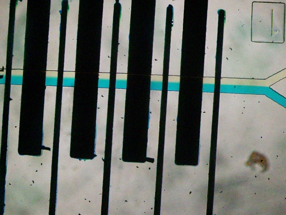
Figure 1: EHD micromixer with bottomwall al electrodes.
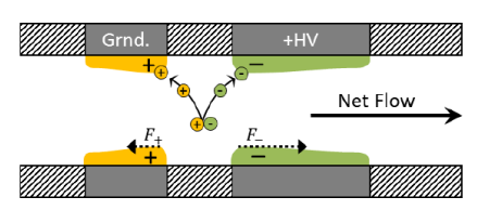
Figure 2:Coulomb force acting on the flow
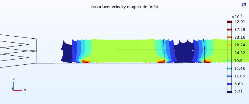
Figure 3: The representation of vortices with iso-surface.
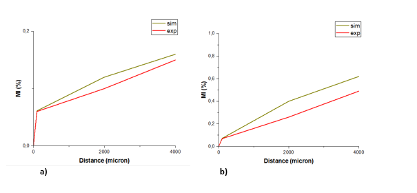
Figure 4: Mixing index values with the applying voltage a)5, b)15.
Passive Micromixing
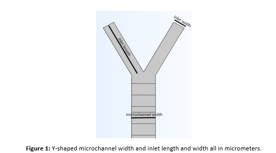
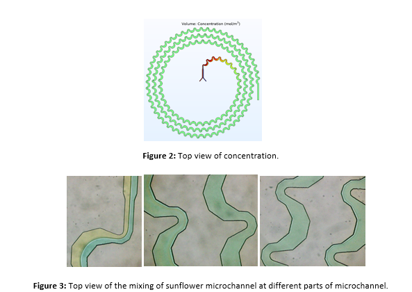
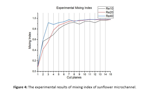
Passive micromixing occurs via molecular diffusion between different fluids. The mixing quality called mixing index depends on the shape of the microchannel and the flow rate of the fluids. In figure 1, the Y-shaped microchannel causes the laminar flow, which provides the mixing by molecular diffusion of the fluids. The higher the flow rate causes the smaller contact area between the fluids. This leads to lower degree of molecular diffusion and mixing index. On the contrary, the lower the flow rate leads to larger contact area between the fluids, and higher mixing index. Figure 2 displays the sunflower microchannel design, and figure 3 is the microscopic image during the microfluidic experiments. This design causes the formation of turbulent flow. Instead of molecular diffusion, chaotic advection increases the mixing more. Unlike laminar flow, the flow rate is inversely proportional to the mixing index. Figure 4 indicates the relationship between Re number and mixing index.
Particle Separation
Cell separation in microfluidic devices by means of hydrodynamic forces has been widely recognized for its practicality, versatility, simple design and high efficiency. As the particle-carrying fluid is introduced into the inertial microfluidic system, the particles undergo two dominant forces – the inertial lift force (FL) and the Dean drag force (FD) – under which their trajectories within the channel change, and thus, they tend to migrate laterally towards locations at which they would focus and maintain their positioning downstream. We have successfully employed these techniques to separate particles in microchannels by dean flow and inertial effects as seen in Fig. 1 and Fig.2, respectively.
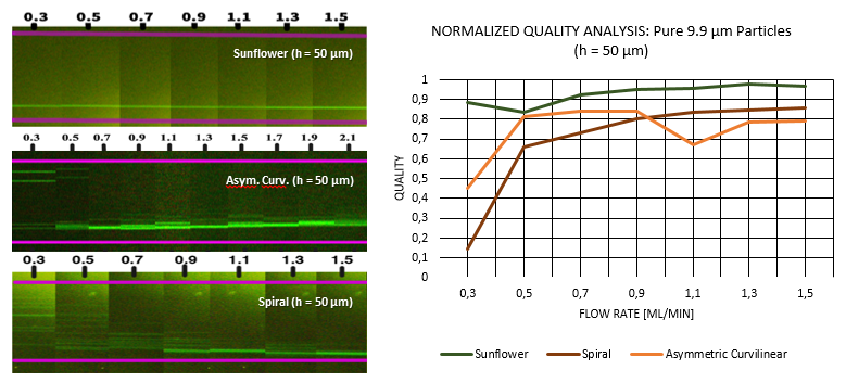
Fig. 1: (Left) successive images of the focusing process of pure 9.9 μm particles in each microchannel as the flow rate increases (Right) Graph showing the variation in focus quality as the flow rate increases in each of the microchannels.
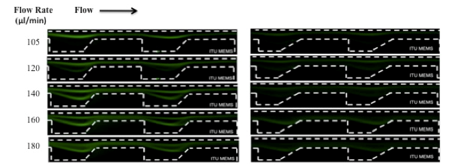
Fig. 2: Variation in particle movement and focusing with increasing flow rates by means of inertial effects.
Cell Separation
Cell separation based on size by microfluidic devices has become a widely studied research area to facilitate the diagnosis of malaria and cancer, in particular. Conventional diagnostic systems are sophisticated but expensive; however, with microfluidic devices a broad range of laboratory applications can be accomplished in a hand-held device. We fabricated a series of devices as Dean force-coupled curved mirochannels for separation of human breast cancer cell lines, MCF-7 ( ̴ 20 µm ) and MD-MBA-231 ( ̴ 15 µm) as seen in Fig. 1. We have also successfully separated Jurkat cells from the medium by means of DEP principle (Fig. 2).
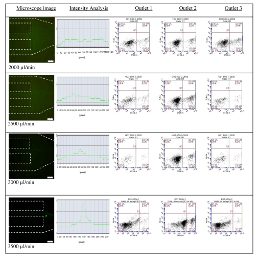
Fig. 1: Experimental data for 600 μm wide channel with a different flow range from 2,000 to 3,500 μl/min, presenting regime changes from unfocussed to focused one.
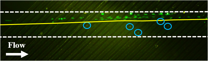
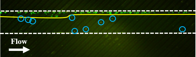
Fig. 2: Experimental results for Jurkat cells. The enrichment of cells is expressed with yellow line and the microchannel sidewalls are expressed with white dash. Cells with larger diameters are focused on the one side of microchannel along microelectrode geometry and cells with smaller diameter (expressed with blue circles) are not affected by a dominant dielectrophoretic force.
DEP
Dielectrophoresis (DEP) is a well-known process to manipulate/separate a target cell types in complex populations and even capturing cells in an active electrical traps in a single array form. DEP is based on a force acting on a dielectric particle when it is subjected to a non-uniform electric field of either DC or AC. A dielectric particle polarises under a non-uniform electric field and there is a net dipole moment acting on it. Each type of cells has a unique polarisability, size and viability, which makes the method useful for a target cell manipulation. Detection of early stages of cancer diseases by cost effective DEP based Lab-on-a-Chips is a good alternative to commercially available Fluorescence activated cell sorting (FACS) and Magnetic activated cell sorting (MACS) methods that offer high performance but require expensive infrastructure and reagents. Separation of polistyrene particles in different diameters by DEP is presented below.
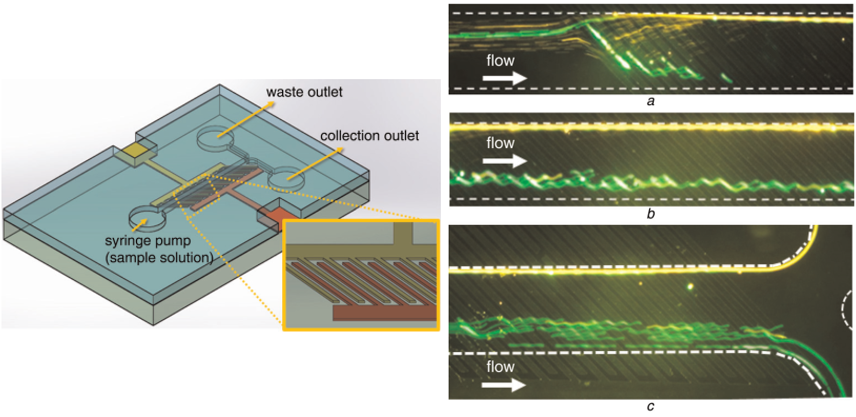
Fig: (Left-hand side) - Schematic representation of a designed microsystem for enrichment of biological particles. Interdigitated titanium microelectrodes are aligned on bottomside of the microfluidic channel (Right-hand side) Separation of polystyrene particles in different diameters. Particles are focused on one side of the channel at the beginning with a buffer inlet. a) Particles are 9.8 µm (green) are deflected along the microelectrodes b) 3.2 µm (red) particles are collected from the waste outlet without any deflection c) White dash represents the microchannel sidewalls).
Lab-on-a-chip
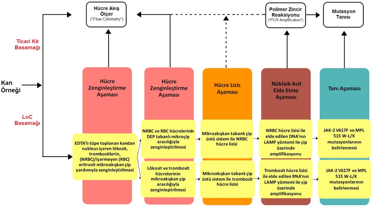
Lab-on-a-chip (LoC) is a microfluıdics based system, in which there are several consecutive stages of whole process in order to imitate fully functional lab procedures. LoCs are used in biomedical and environmental applications, such as, fluid transport, drug delivery, diagnosis of viruses and bacteria and manipulation of particles for focusing and separation applications. We have developed several such systems based on expertise developed in the field of particle/cell enrichment/separation by means of inertial and DEP based microfluidics. We have developed several systems one of which is the diagnostic kit for sensitive and rapid diagnosis of tuberculosis infection, as seen in Fig. 1.
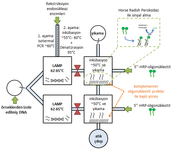
The other promising example is the development of fast and sensitive diagnostics-kit for myeloproliferative neoplasms, as seen in Fig. 2. Both systems are complex at the three junction interfaces of medicine, engineering and chemistry so that it is possible to analyze raw biological substance to observe any targeted indication.
Mechanobiology
Unlike conventional methods, performing cell culture applications by microfluidics systems are being preferred by researchers in terms of reducing required amount of sample, agents and decreasing time and cost. By the way, being portable and not to require expertise are the other factors of the reason of preferring microfluidics systems in biology.
Cells in body are subjected to internal and external stimulations play major role in cell processing such as growth, division, migration and apoptosis (Figure 1). One of these stimulations is defined as shear stress that is the force that blood flow applying on the unit area and endothelial cells lining through vessel wall are exposed to different flow conditions because of changing in shear stress levels and grades. In this content, the effect of shear stress by laminar flow on HUVECs (Human Umbilical Vein Endothelial Cells) is aimed to be investigated in the microfluidics system.
As shown in Figure 2, HUVEC cell line are seeded into microfluidic system and then biological responses are investigated under various fluid flow after treating with Oxidized LDL (ox-LDL) or Tumor Necrosis Factor-α (TNF-α) as compatible with atherosclerotic model.
Briefly, it is aimed that biological responses against to shear stress in various flow levels are investigated in molecular level. It is suggested that obtained results can provide positive contributions in designing medicine and bioimplants.
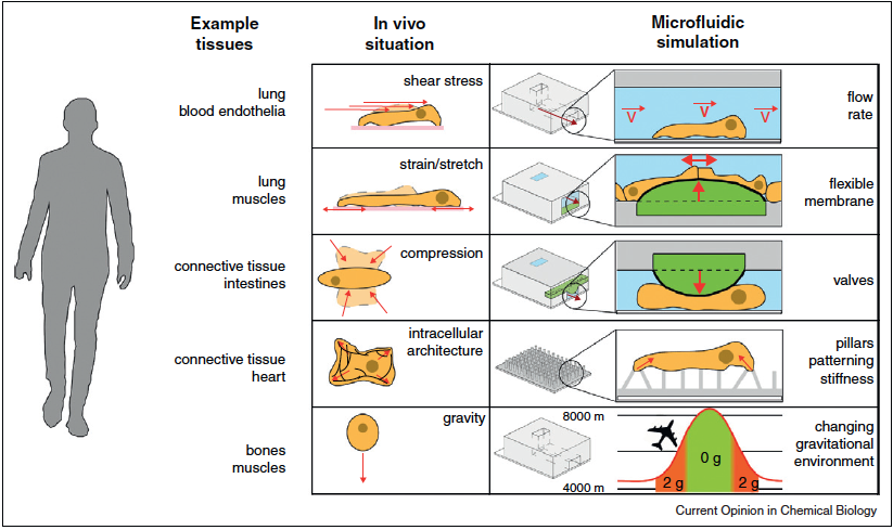
Fig. 1: Schematic of mechanical forces exposes continuously to cells in human body and microfluidics systems that mimic these forces in different ways.
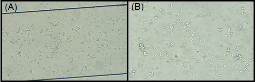
Fig. 2: The micrograph of HUVEC cells seeded into microchannel, 5X magnification; (A), 10X magnification (B).
MicroPump Design and Fabrication
This study presents design and construction of a peristaltic micropump that can be integrated with various applications of microfluidics. The design aimed an easy-to-use peristaltic micropump that is coherent with diverse PDMS based microfluidic applications. The design is manufactured by additive manufacturing. In our case with, a tiny reprogrammable signal generator is fitted into the pump, in order to use a dielectrophoretic chip in it. The micropump precludes use of traditional syringe pumps and cumbersome signal generator. Therefore, the device enables the use of lab-on-a-chip (LoC) systems for point-of-care (PoC) applications as well as for laboratory applications.
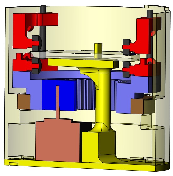
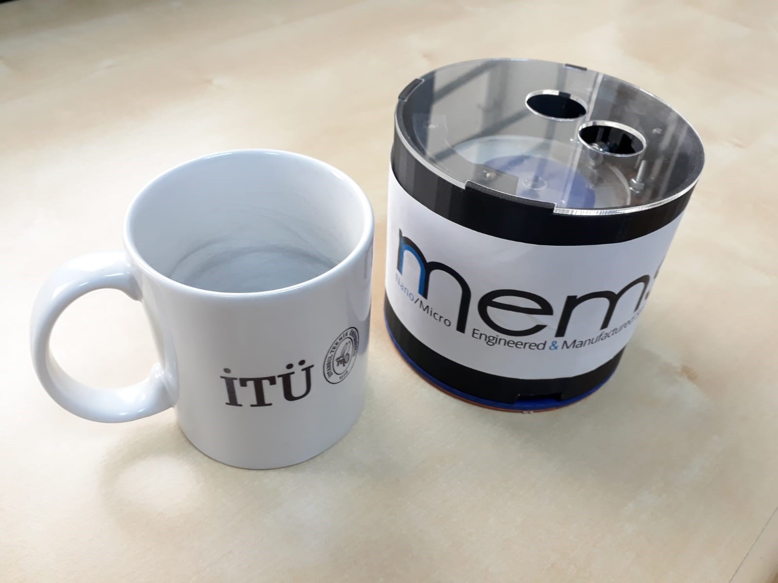
Fig. 1: The section view of the design and comparison of the product with a cup.
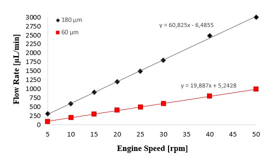
Fig. 2: The flow rate output the pump with altering rotary speed.
3-D DEP
Among numerous manipulation and characterization of biological particles and circulating tumor cells (CTCs), electrical methods have very significant advantages such as being label-free and noninvasive in LoC applications. The dielectrophoresis (DEP) technique is frequently preferred one in LoC devices in clinical application. In this project, we aim to apply composite of Carbon nanotubes (CNT) and Polydimethylsiloxane (PDMS) in DEP separation channels, which promises a cheaper, more efficient and flexible electrode by bringing nano approach to microchannels. The composite not only develops a 3D channel instead of a logy 2D, but also diminishes the effort of making electrodes from clunky lift-off processes to a simple syringe injection method.
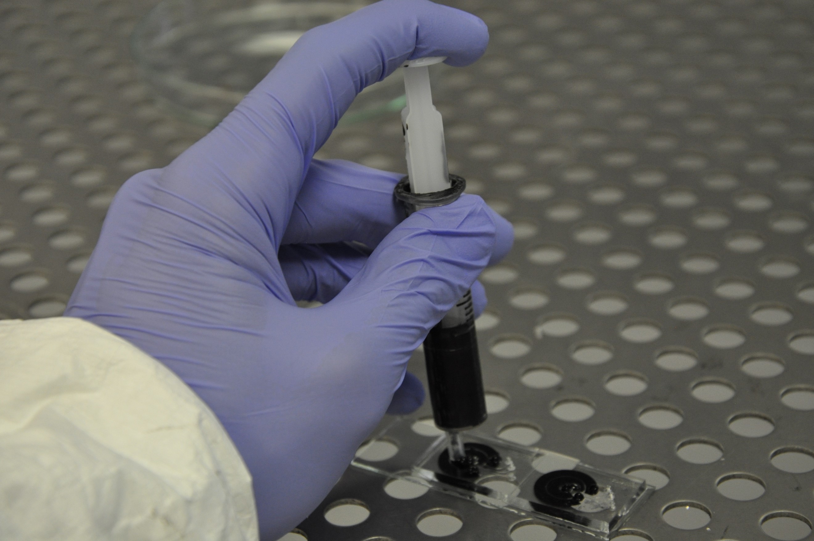
Fig. 1: Manufacturing of electrodes by injection.
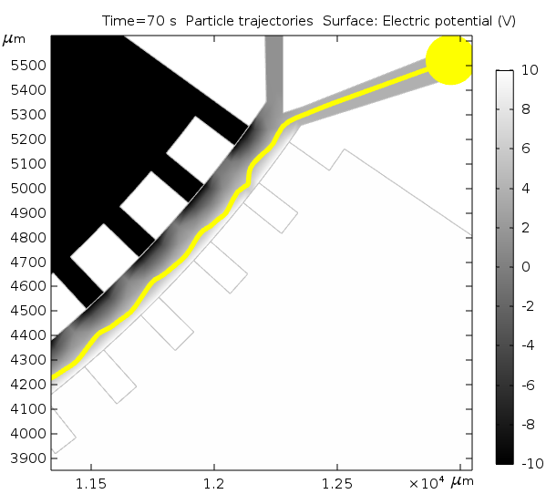
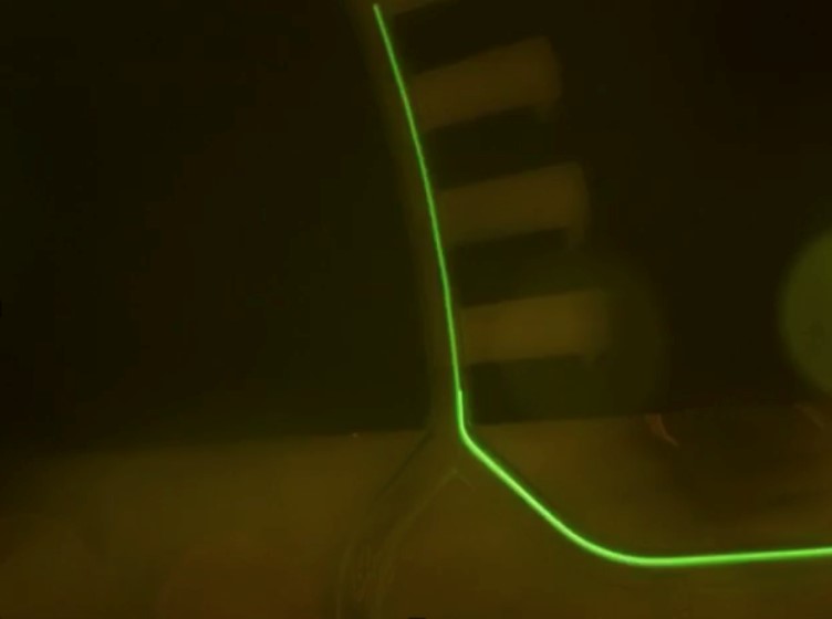
Fig. 2: Simulation and Characterization of the chip.
Design and Fabrication of Quantum Dots-based Optical Immunosensor in Microfluidic System
In microfluidic system, using carrier microbead and trapping them on appropriate microtraps is an alternative way to create a detection area. With this scope, an optical biosensor platform will be created in a microfluidic system with quantum dots decorated microbeads to detect aflatoxin B1. The most important aspect of this study is the detection of optical changes that will occur as a result of antibody-antigen interaction on polystyrene microspheres (PSMSs) which are modified with QD on an easy and portable platform. Microsphere structures encoded with QDs increase the stability of the QDs for immunosensor applications within the most appropriate designed microfluidic channel in order to benefit from high efficiency
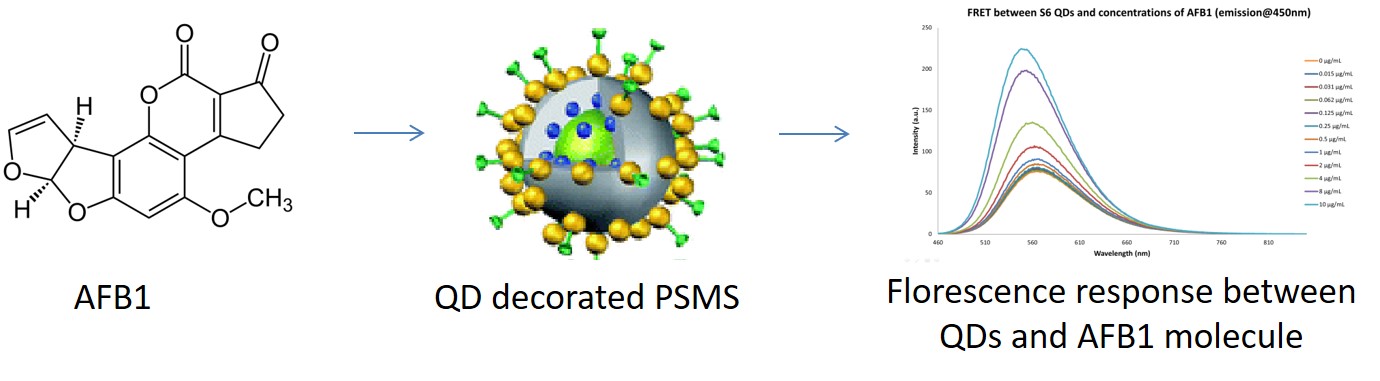
Design a portable microfluidic system and fabrication by integrating with fiber optic spectroscopy and peristaltic pump.